 | –≠–ª–µ–∫—Ç—Ä–æ–Ω–Ω—ã–π –∫–æ–º–ø–æ–Ω–µ–Ω—Ç: BC807-25 | –°–∫–∞—á–∞—Ç—å:  PDF PDF  ZIP ZIP |
3
BC807-16
BC807-25
BC807-40
PNP General Purpose Amplifier
This device is designed for general purpose amplifier and switching
applications at currents to 1.0 A. Sourced from Process 78.
Absolute Maximum Ratings*
TA = 25∞C unless otherwise noted
*
These ratings are limiting values above which the serviceability of any semiconductor device may be impaired.
Thermal Characteristics
TA = 25∞C unless otherwise noted
Symbol
Characteristic
Max
Units
*BC807-16 / -25 / -40
P
D
Total Device Dissipation
Derate above 25
∞
C
350
2.8
mW
mW/
∞
C
R
JA
Thermal Resistance, Junction to Ambient
357
∞
C/W
Symbol
Parameter
Value
Units
V
CEO
Collector-Emitter Voltage
45
V
V
CES
Collector-Base Voltage
50
V
V
EBO
Emitter-Base Voltage
5.0
V
I
C
Collector Current - Continuous
1.2
A
T
J
, T
stg
Operating and Storage Junction Temperature Range
-55 to +150
∞
C
C
B
E
SOT-23
Mark: 5A. / 5B. / 5C.
*
Device mounted on FR-4 PCB 40 mm X 40 mm X 1.5 mm.
1997 Fairchild Semiconductor Corporation
BC807-16 / BC807-25 / BC807-40
NOTES:
1) These ratings are based on a maximum junction temperature of 150 degrees C.
2) These are steady state limits. The factory should be consulted on applications involving pulsed or low duty cycle operations.
3) All voltages (V) and currents (A) are negative polarity for PNP transistors.
Electrical Characteristics
TA = 25∞C unless otherwise noted
OFF CHARACTERISTICS
Symbol
Parameter
Test Conditions
Min
Max
Units
ON CHARACTERISTICS
h
FE
DC Current Gain
I
C
= 100 mA, V
CE
= 1.0 V
- 16
- 25
- 40
I
C
= 500 mA, V
CE
= 1.0 V
100
160
250
40
250
400
600
V
CE(
sat
)
Collector-Emitter Saturation Voltage
I
C
= 500 mA, I
B
= 50 mA
0.7
V
V
BE(
on
)
Base-Emitter On Voltage
I
C
= 500 mA, V
CE
= 1.0 V
1.2
V
V
(BR)CEO
Collector-Emitter Breakdown Voltage
I
C
= 10 mA, I
B
= 0
45
V
V
(BR)CES
Collector-Base Breakdown Voltage
I
C
= 100
µ
A, I
E
= 0
50
V
V
(BR)EBO
Emitter-Base Breakdown Voltage
I
E
= 10
µ
A, I
C
= 0
5.0
V
I
CBO
Collector-Cutoff Current
V
CB
= 20 V
V
CB
= 20 V, T
A
= 150
∞
C
100
5.0
nA
µ
A
NOTE: All voltages (V) and currents (A) are negative polarity for PNP transistors.
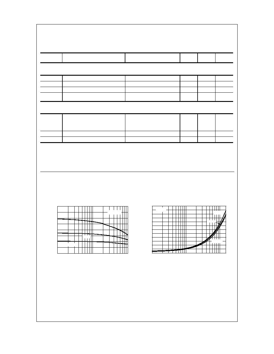
Typical Characteristics
Collector-Emitter Saturation
Voltage vs Collector Current
0.01
0.1
1
1.5
0
0.1
0.2
0.3
0.4
0.5
0.6
I - COLLE CTOR CURRENT (A)
V
-
C
O
LL
E
C
TO
R
-
E
M
I
TTE
R
V
O
LT
A
G
E
(
V
)
C
ESA
T
C
= 10
125 ∞C
- 40 ∞C
25 ∞C
Typical Pulsed Current Gain
vs Collector Current
0.01
0.1
1
0
100
200
300
400
I - COLLECTOR CURRENT (A)
h
-
TY
P
I
C
A
L P
U
LS
E
D
C
U
R
R
E
N
T
G
A
I
N
FE
- 40 ∞C
25 ∞C
C
V = 5V
CE
125 ∞C
BC807-16 / BC807-25 / BC807-40
PNP General Purpose Amplifier
(continued)
3
BC807-16 / BC807-25 / BC807-40
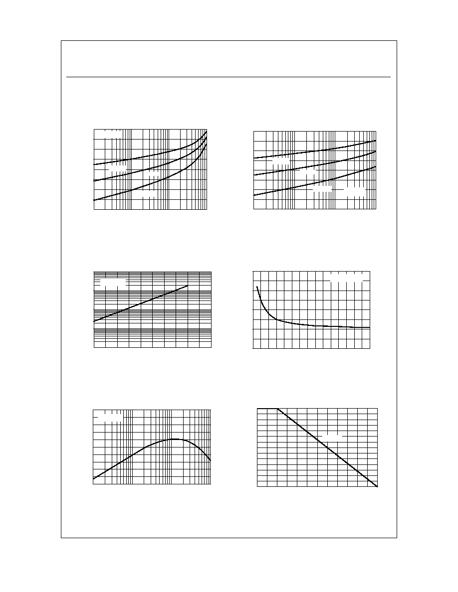
Power Dissipation vs
Ambient Temperature
0
25
50
75
100
125
150
0
50
100
150
200
250
300
350
TEMPERATURE ( C)
P
-
POW
E
R DI
SSIP
A
TION (
m
W
)
D
o
SOT-23
PNP General Purpose Amplifier
(continued)
Typical Characteristics
(continued)
Collector-Base Capacitance
vs Collector-Base Voltage
0
4
8
12
16
20
24
28
0
10
20
30
40
V - COLLECTOR-BASE VOLTAGE (V)
-
CO
L
L
E
C
T
O
R-
B
A
SE
C
A
PA
C
I
T
A
NC
E
(
p
F
)
CB
obo
f = 1.0 MHz
Gain Bandwidth Product
vs Collector Current
1
10
100
1000
0
50
100
150
200
250
I - COLLECTOR CURRENT (mA)
h
-
G
A
I
N
B
A
ND
W
I
DTH
PR
O
D
U
C
T
(
M
Hz
)
C
FE
V = 10V
CE
Collector-Cut off Current
vs Ambient Temperat ure
25
50
75
100
125
150
0.1
1
10
100
T - AM BIENT TE MPE RATURE ( C)
I
-
C
O
L
L
E
CT
O
R
CU
RRE
NT
(
n
A)
A
V = 4 0V
CB
∞
CB
O
Base-Emitter Saturation
Voltage vs Collector Current
1
10
100
1000
0.4
0.6
0.8
1
I - COLLECTOR CURRENT ( mA)
V
-
B
A
S
E
-
E
M
I
T
T
E
R
V
O
L
T
A
G
E
(
V
)
BE
S
A
T
C
= 10
125 ∞C
- 40 ∞C
25 ∞C
Base-Emitter ON Voltage vs
Collector Current
1
10
100
1000
0.2
0.4
0.6
0.8
1
I - COLLECTOR CURRENT (mA)
V
-
B
A
S
E
-
E
M
IT
T
E
R
O
N
V
O
L
T
A
G
E
(
V
)
BE
(
O
N)
125 ∞C
- 40 ∞C
25 ∞C
C
V = 5V
CE
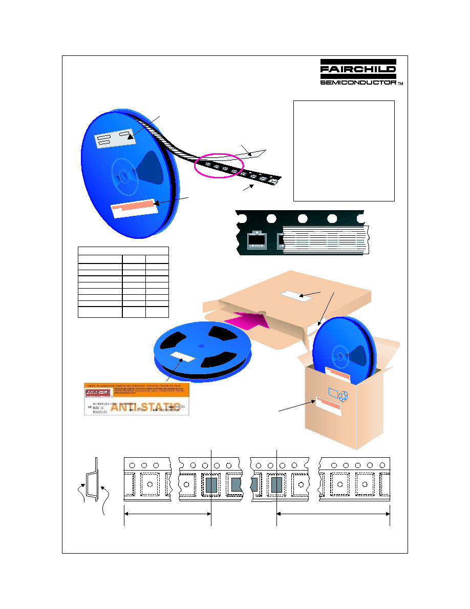
SOT-23 Packaging
Configuration: Figure 1.0
Components
Leader Tape
500mm minimum or
125 empty pockets
Trailer Tape
300mm minimum or
75 empt y poc kets
SOT-23 Tape Leader and Trailer
Configuration: Figure 2.0
Cover Tape
Carrier Tape
Note/Comments
Packaging Option
SOT-23 Packaging Information
Standard
(no flow code)
D87Z
Packaging type
Reel Size
TNR
7" Dia
TNR
13"
Qty per Reel/Tube/Bag
3,000
10,000
Box Dimension (mm)
187x107x183
343x343x64
Max qty per Box
24,000
30,000
Weight per unit (gm)
0.0082
0.0082
Weight per Reel (kg)
0.1175
0.4006
H uman readable
Label
Human Readable Label
Human Readable Label sample
343mm x 342mm x 64mm
Intermediate box for L87Z Option
187mm x 107mm x 183mm
Intermediate Box for Standard Option
SOT-23 Unit Orientation
3P
3P
3P
3P
Human Readable
Label
Customized Label
Embossed
Carrier Tape
Antistatic Cover Tape
Packaging Description:
SOT-23
made from a dissipative (carbon filled) polycarbonate
resin. The cover tape is a multilayer film (Heat Activated
Adhesive in nature) primarily composed of polyester film,
adhesive layer, sealant, and anti-static sprayed agent.
These reeled parts in standard option are shipped with
3,000 units per 7" or 177cm diameter reel. The reels are
dark blue in color and is made of polystyrene plastic (anti-
static coated). Other option comes in 10,000 units per 13"
or 330cm diameter reel. This and some other options are
described in the Packaging Information table.
These full reels are individually labeled and placed inside
a standard intermediate made of recyclable corrugated
brown paper with a Fairchil d logo printing. One pizza box
contains eight reels maximum. And these intermediate
boxes are placed inside a labeled shipping box which
comes in different sizes depending on the number of parts
shipped.
parts are shipped in tape. The carrier tape is
SOT-23 Tape and Reel Data
September 1999, Rev. C
©2000 Fairchild Semiconductor International
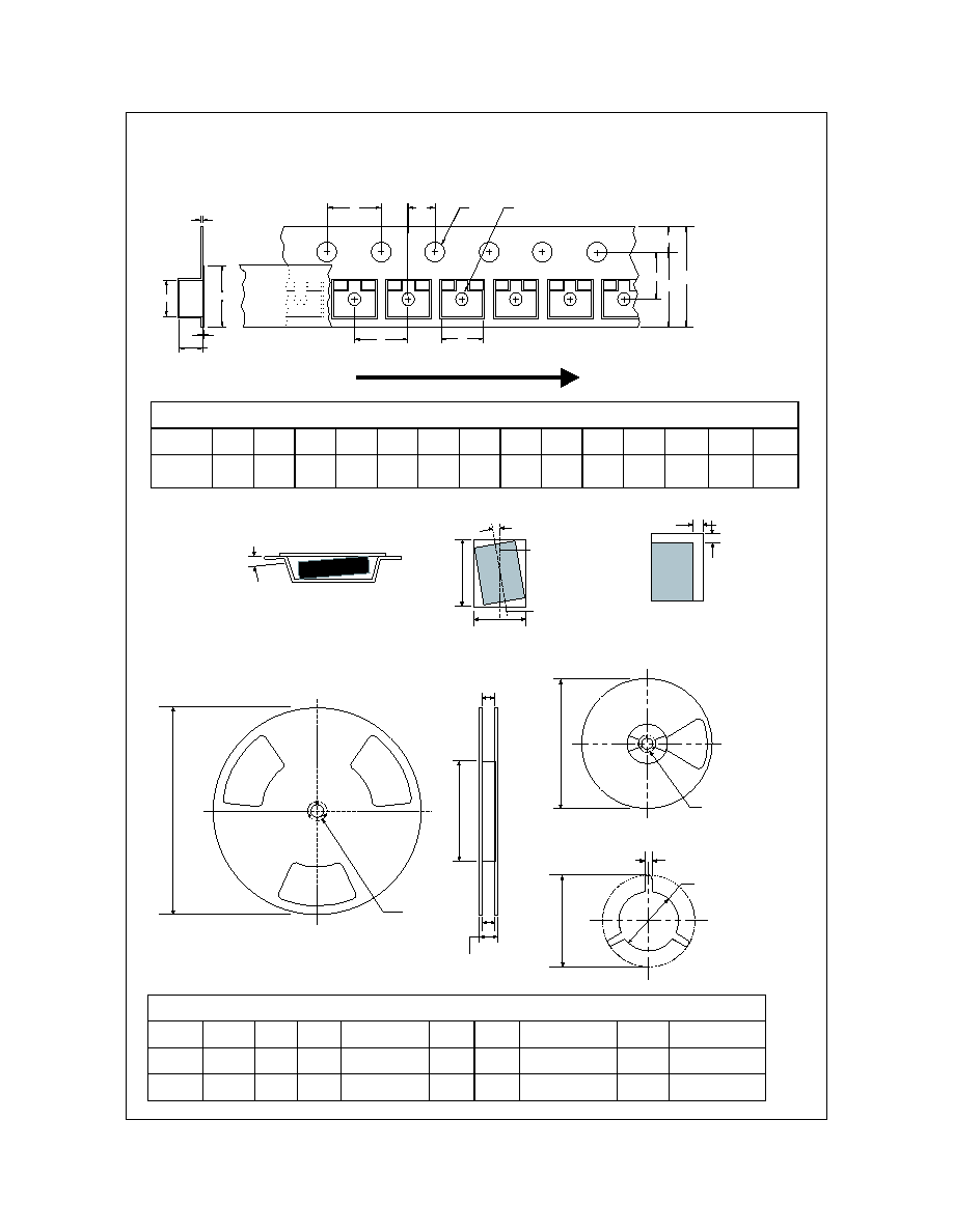
Dimensions are in millimeter
Pkg type
A0
B0
W
D0
D1
E1
E2
F
P1
P0
K0
T
Wc
Tc
SOT-23
(8mm)
3.15
+/-0.10
2.77
+/-0.10
8.0
+/-0.3
1.55
+/-0.05
1.125
+/-0.125
1.75
+/-0.10
6.25
min
3.50
+/-0.05
4.0
+/-0.1
4.0
+/-0.1
1.30
+/-0.10
0.228
+/-0.013
5.2
+/-0.3
0.06
+/-0.02
Dimensions are in inches and millimeters
Tape Size
Reel
Option
Dim A
Dim B
Dim C
Dim D
Dim N
Dim W1
Dim W2
Dim W3 (LSL-USL)
8mm
7" Dia
7.00
177.8
0.059
1.5
512 +0.020/-0.008
13 +0.5/-0.2
0.795
20.2
2.165
55
0.331 +0.059/-0.000
8.4 +1.5/0
0.567
14.4
0.311 ≠ 0.429
7.9 ≠ 10.9
8mm
13" Dia
13.00
330
0.059
1.5
512 +0.020/-0.008
13 +0.5/-0.2
0.795
20.2
4.00
100
0.331 +0.059/-0.000
8.4 +1.5/0
0.567
14.4
0.311 ≠ 0.429
7.9 ≠ 10.9
See detail AA
Dim A
max
13" Diameter Option
7" Diameter Option
Dim A
Max
See detail AA
W3
W2 max Measured at Hub
W1 Measured at Hub
Dim N
Dim D
min
Dim C
B Min
DETAIL AA
Notes: A0, B0, and K0 dimensions are determined with respect to the EIA/Jedec RS-481
rotational and lateral movement requirements (see sketches A, B, and C).
20 deg maximum component rotation
0.5mm
maximum
0.5mm
maximum
Sketch C (Top View)
Component lateral movement
Typical
component
cavity
center line
20 deg maximum
Typical
component
center line
B0
A0
Sketch B (Top View)
Component Rotation
Sketch A (Side or Front Sectional View)
Component Rotation
User Direction of Feed
SOT-23 Embossed Carrier Tape
Configuration: Figure 3.0
SOT-23 Reel Configuration: Figure 4.0
P1
A0
D1
F
W
E1
E2
Tc
Wc
K0
T
B0
D0
P0
P2
SOT-23 Tape and Reel Data, continued
September 1999, Rev. C